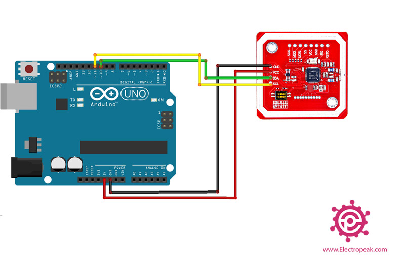
Read the WHO_AM_I register and print the result This will set the Arduino up as the 'Master' device. Create a serial connection using a 9600bps baud rate. In the setup section of the sketch the serial port will be configured, the i2c communication will be initialized, and the itg-3200 will be configured. the jumper on top of the board is configured. By default, the jumper is connected to the VDD pin. When the jumper is connected to the VDD pin the I2C address

I2C devices each have an address. The address is defined in the datasheet for the device. The ITG-3200 breakout board can have different address depending on how FS_SEL must be set to 3 for proper operation This is a list of settings that can be loaded into the registers.

To learn more about the registers on the ITG-3200, download and read the datasheet. This is a list of registers in the ITG-3200. Registers are parameters that determine how the sensor will behave, or they can hold data that represent the The Wire library is used for I2C communication Soldered GND and CLK to the ground and INT floating, Connected 2 external pull ups with 10K to the 1.7 and 1.6 ports to SDA and SCL. Gyro input VLogic had to be smaller than VDD at all times for the voltage difference so i serial connected 2 10K resistors and get 1.75V between them to the VLogic.

Since gyro is working near 3V and luckily 2553 has the same output VCC i had no problems with that. This is the gyro product that i'm using and they also provided an Arduino example here After i struggle a lot in the MSP registers, i found it easier to use the Arduino libraries which provides a lot on wire so thanks to energia As i mentioned previously in another discussion, i have a project that has an ITG3200 digital output gyroscope that communicates through I2C.


 0 kommentar(er)
